Sunday, July 14, 2019

Wow.  More than two years since the last blog post.  Sorry about that.

Finally have the 427 series 2 wired and running on the test stand.  You all saw the build of this back in 2016.  In the meantime, I have chosen an aftermarket, motorsport-grade Engine Management System... The Life Racing F88 ECU.  This is a professional level ECU, used in countless sports cars and touring car series.  It has twin CPUs, one for the time-sensitive engine angle clock, and the other for the various inputs/outputs controlled by the ECU.  In my case, I'm running 16 sequentially fired injectors, staged.  The primaries will fuel the engine up to about 30% duty cycle, then I'll bring in the secondaries gradually from that point.

Also, a first, this engine is running sequential Coil near Plug ignition coils.  I could not find a plug-top boot that I was happy with the fit, so I mounted 8 individual coils under the plenum.  Each feeds a custom plug wire for it's particular cylinder.  These Bosch coils are the same ones used on current Nascar (Winston, Nextel, Sprint, Monster...) Cup engines.

The custom wiring harness was a joint project with Indy Wiring Services.  All mil-spec wires and connectors.  Jeremy Gibson is a true professional , and excellent to work with.  Overall, the harness turned out great.  Could have been 1/2" here or there, but for my amateur measurements, a good fit nonetheless.  All Raychem covered, glue-lined shrink boots, etc.

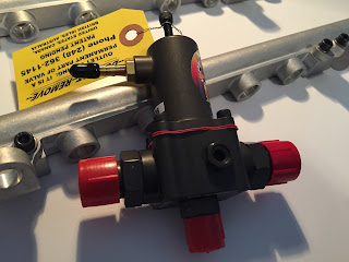
What you see here doesn't have the Kinsler fuel rails and racing pressure regulator.  My previous testing revealed some issues with tuning that setup.  Simply need more time to troubleshoot it and tune it.

Running on a "from-scratch" calibration, the ECU successfully ran the engine.  That is, once I fixed the cam sync.  Initially I had the cam tooth 360* out of phase, so the motor would not run on 720-sequential.  Easy fix (675-360 = 315 degrees cam sync).  And boom!  The motor fired up.

I had the idle screw pretty far open to get the motor started, so it idled around 2000 rpm.  At this point I don't have the Idle Control valve connected or configured, so I just needed enough throttle opening to get it to run on it's own.  I have to say, even with a very rough calibration, the motor barked.  With the speed of the processors, and the precision of control, I've never heard an LT5 sound so sweet on the stand.  Flicking the throttle blades rev'ed the motor instantly.  I can't wait to get this thing fine-tuned.

Anyway, next time I'll video the engine running.  For now here's a few pics and a walk-around video.


Sunday, July 2, 2017

First start

Got the new engine started today.  A registry member came by to experience it with me, which was cool.  Prior to today, I filled her up, and pressurized the oil galleries with Joe Gibbs BR30 break-in oil.  Filled the radiator, and fitted the Dynomax mufflers to keep the neighbors happy--only slightly.

First crank, fired up pretty quick.


It's very hard to get these motors to burp the air out of the cooling system on the stand.  I have not (yet) tapped bleed fittings in the coolant outlet pipes on this engine.  I have however already blocked off the coolant passage in the plenum.  Passenger side had good water circulation, but the driver's side did not.  Coolant pipe would not get hot enough to indicate water flowing out from that side.  After this first start, I disconnected the 90-degree elbow from the drivers side and forced air into the system, blowing into the coolant crossover tube until hot water finally came out from the driver's outlet pipe.

You might also see smoke from the exhaust on the driver's (left) side.  When I pressurized the system, I forgot to install the cam sensor, and the resulting oil leak poured down on the exhaust header.  Doh!  Will take some time and heat cycles to burn off all the oil residue.

Here's another video I took later in the day,


After it all cooled down, I performed a cranking compression check, and cylinder leakdown test.  The cranking compression for all cylinders was remarkably consistent, just over 240 psi-- a good jump over Build1. Leakdown rates were even more impressive.  All cylinders were less than 2%, despite not yet getting any load on the rings to seat them in properly.  There was much worse and scattered leakage values on the old build.  All over the map, 6% to 18%.  I am going to give credit to Ross pistons, Total Seal rings, and the machine shop for nailing the cylinder finish.

Oil pressure was ~60psi at idle, and the wideband indicated we were a little lean, but that might be a function of the cam overlap at idle.  Once I opened the throttle and brought the revs up, it richened up.  Alternator isn't charging, so I need to figure that out, but otherwise I'd call it a successful day.  Now off to the dyno!


Monday, June 12, 2017

Getting Closer.....

Getting closer to the first fire!


Cams timed.  109/111 centers.  A degree allowance for wear/chain stretch.  Using the new high strength cam chains co-developed with Jerry.  I've now got the new build on the test stand to finish assembly and fire it up.  Hope we can have a local get-together when the time comes.  Then off to the engine dyno!


Minor issue with the new fuel rails.  I need a very low profile 90-degree elbow to clear the throttle linkage on the driver's side.  It's a very tight space to run the crossover line from left rail to right.  I plan to fire it up with the stock rails until I can sort out the new parts.

Also, replacing all the plenum vacuum nipples with NPT pipe fittings.  Pics to follow.


Saturday, February 25, 2017

New Fuel Rails and PRV

As I said in a previous blog post, we had trouble getting enough fuel to the first 427 build at 700 chp.  I believe the fuel system was not up to the task, so contracted Kinsler to develop new rails capable of feeding more than 800 chp.  These are custom made and feature .685" ID, with -8AN inlets and outlets.

I will have to run new lines from the pumps to the rails.  Will feed the fuel inlet into the drivers side with -8AN line.  Connect the two rails in the front--there is no A/C compressor in the way, so plenty of room to route the line.  At the end of the passenger side rail, I will connect the pressure relief valve, set to 75psi.  A -6AN return line will send the excess fuel back to the tank.

With the relief valve set to 75psi, my 30lb Red Motorsport injectors will flow the equivalent of 44 lbs/hr-- enough for over 1000chp.


Saturday, January 7, 2017

Mid-winter update

You guys are probably wondering where I've gone.  No posts since September on this project.  Had to spend some time doing other things in the fall, and now it's just too damn cold out in the shop to do much.  Nonetheless, some things are moving forward.

  • The cylinder heads are installed on the shortblock, torqued to 120 lbs-ft (ARP studs).  Cams and lifters are in place, temporarily.

  • Degree wheel is installed, ready to time the camshafts.
On the advice of my camshaft supplier, I will slightly modify the cam timing to suit the new intake flows and higher compression (14.5:1 from 12:1).  New timing will be ICL: 109 ATDC / ECL: 111 BTDC.  This compares to 107/109 on the first build.  Perhaps idle quality will be a touch better with the less valve overlap.

  • Fuel system design continues.  This includes new rails with larger ID, and a new regulator to bump fuel rail pressure to 75 psi.  The Bosch series III injectors handle that pressure just fine, and the better atomization should help combustion efficiency.  We will feed the rail with -8 supply lines (1/2" ID).

  • Crankcase evacuation strategy continues to develop.  I am convinced the main issue with the previous build causing oil in the combustion chambers, was due to the flow through the stock PCV system.  At idle the manifold vacuum was sufficiently low (~60-65 kpa) to prevent the valves from closing, thus allowing significant oil and vapor back into the intake manifold.  This time around, I plan to vent the crankcase directly to a catch can.  I'd appreciate feedback from anyone who's done this.  I know it was done successfully on a recent LT5 for racing application.  At 14.5:1 compression, the combustion chambers have to be oil-free.

  • The calibration and datalogging setup continues to mature.  I will initially use Tunerpro RT with a custom dash, including a new ALDL stream to monitor exactly the variables I want (such as commanded Lambda).  A NTK wideband output, and a dedicated fuel pressure sensor will be fed into the stock ECM for monitoring.

  • And lastly, in a few weeks the top end pieces (plenum, airhorn, cam covers) will be going out for powdercoating.  Not real urgent on that one.

Until next time.

Monday, September 12, 2016

Cylinder Head assembly

This installment will detail the set-up and assembly of the cylinder heads, including valves and valve springs.  One of the most time-consuming element of the entire build, careful attention to detail is required here to ensure the valvetrain is durable and remains in control at high engine speeds.  Here are the springs and components.  Eibach single springs, titanium retainers, hardened steel spring seats, locks and shims.
I've posted before about the tedious work to shim the valvesprings.  At the bottom of this picture is the coated steel shim.  I got hundreds of these NASCAR take-off shims from Ebay for next to nothing, they work great.  First step was measuring the valve stem height from the base of the spring pocket.  I didn't take pictures of that, but it requires a simple cylindrical aluminum fixture with a 1" dial indicator at the top.  I used a 2" standard to set the initial gage height, then the actual height of the stem is measured.  Other inputs you need to set up the spring heights are the thickness of the spring seat (.040" in my case), and the retainer to tip distance (.150").  My valve stem heights were: 1.5825"-1.5895" intake, and 1.581" to 1.591" exhaust.

Next step was to install the new valve stem oil seals, and lubricate the valves with Torco.  These oil seals are low profile, so will clear very high lift cams.

Before putting it all together, I used this valve spring tester to make sure all of the springs were still in spec.  Measured a brand new one, then checked all 32 against that standard.  Variation was minimal, and all were within spec, however, I did replace the three weakest ones just for peace of mind.  Weak in this case was 5 pounds lower than the others.  Probably would have been fine.  I set both intake and exhaust springs up to .060" from their coil bind height.  That required approximately .020" shims on the intakes and .050" shims on the exhaust.  In this case, the intake spring force will be about 6 pounds higher than the first build, and the exhaust about the same.  Intakes are now 63 lbs closed, and 172 lbs open / exhausts are 69 and 173 lbs.


And here is the finished product, ready to install on the shortblock.


Sunday, September 4, 2016

Setting valve spring heights

Not much to report lately.  I have paused the engine assembly while I get the top end ready for installation.  As it stands, the short block is ready to go.

As anyone who's used the ARP head studs know, one of the studs on the exhaust side needs clearancing for the cam sensor disc.  In my case, I need .060" taken off.  From what I've heard from other builders, this varies quite a lot.

I rechecked the piston to deck clearance, and found .003" above the deck.  Much better than I initially thought.  The machinist's deck height measurement must have been off slightly.  Final Comp ratio now 14.55:1

Next major task is setting up the cylinder heads.  New intake valves, so I had to carefully measure the stem height with a fixture and dial indicator.  The valves and seat height were remarkably consistent, yet I still had to shim each intake valvespring to get the exact height.

What a boring way to spend the afternoon.... measuring a few dozen shims.

These were sorted to the nearest .0001".  Probably within the measurement error.  Regardless, I elected to shim the intakes a little closer to coil bind height.  Last time, the intakes were .075" to coil bind.  I intend to rev this engine a bit harder, so I have chosen to set the springs up at .060" to coil bind.  This gives just a tick more spring force throughout the lift curve.

Now the exhaust valves need to be thoroughly cleaned... lots of carbon from the first build.  Then I can set up the exhaust spring heights.  It's a dirty job to de-carbon the valves, no wonder I've been putting it off till now.