Monday, September 12, 2016

Cylinder Head assembly

This installment will detail the set-up and assembly of the cylinder heads, including valves and valve springs.  One of the most time-consuming element of the entire build, careful attention to detail is required here to ensure the valvetrain is durable and remains in control at high engine speeds.  Here are the springs and components.  Eibach single springs, titanium retainers, hardened steel spring seats, locks and shims.
I've posted before about the tedious work to shim the valvesprings.  At the bottom of this picture is the coated steel shim.  I got hundreds of these NASCAR take-off shims from Ebay for next to nothing, they work great.  First step was measuring the valve stem height from the base of the spring pocket.  I didn't take pictures of that, but it requires a simple cylindrical aluminum fixture with a 1" dial indicator at the top.  I used a 2" standard to set the initial gage height, then the actual height of the stem is measured.  Other inputs you need to set up the spring heights are the thickness of the spring seat (.040" in my case), and the retainer to tip distance (.150").  My valve stem heights were: 1.5825"-1.5895" intake, and 1.581" to 1.591" exhaust.

Next step was to install the new valve stem oil seals, and lubricate the valves with Torco.  These oil seals are low profile, so will clear very high lift cams.

Before putting it all together, I used this valve spring tester to make sure all of the springs were still in spec.  Measured a brand new one, then checked all 32 against that standard.  Variation was minimal, and all were within spec, however, I did replace the three weakest ones just for peace of mind.  Weak in this case was 5 pounds lower than the others.  Probably would have been fine.  I set both intake and exhaust springs up to .060" from their coil bind height.  That required approximately .020" shims on the intakes and .050" shims on the exhaust.  In this case, the intake spring force will be about 6 pounds higher than the first build, and the exhaust about the same.  Intakes are now 63 lbs closed, and 172 lbs open / exhausts are 69 and 173 lbs.


And here is the finished product, ready to install on the shortblock.


Sunday, September 4, 2016

Setting valve spring heights

Not much to report lately.  I have paused the engine assembly while I get the top end ready for installation.  As it stands, the short block is ready to go.

As anyone who's used the ARP head studs know, one of the studs on the exhaust side needs clearancing for the cam sensor disc.  In my case, I need .060" taken off.  From what I've heard from other builders, this varies quite a lot.

I rechecked the piston to deck clearance, and found .003" above the deck.  Much better than I initially thought.  The machinist's deck height measurement must have been off slightly.  Final Comp ratio now 14.55:1

Next major task is setting up the cylinder heads.  New intake valves, so I had to carefully measure the stem height with a fixture and dial indicator.  The valves and seat height were remarkably consistent, yet I still had to shim each intake valvespring to get the exact height.

What a boring way to spend the afternoon.... measuring a few dozen shims.

These were sorted to the nearest .0001".  Probably within the measurement error.  Regardless, I elected to shim the intakes a little closer to coil bind height.  Last time, the intakes were .075" to coil bind.  I intend to rev this engine a bit harder, so I have chosen to set the springs up at .060" to coil bind.  This gives just a tick more spring force throughout the lift curve.

Now the exhaust valves need to be thoroughly cleaned... lots of carbon from the first build.  Then I can set up the exhaust spring heights.  It's a dirty job to de-carbon the valves, no wonder I've been putting it off till now.


Saturday, August 13, 2016

Bottom End Assembly

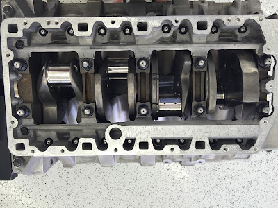
In this installment, the bottom end rotating assembly is assembled.  To start, I again relentlessly wipe the bores down to make sure they are as clean as possible.  Acetone on a white shop rag, followed by Dexron ATF (note: I used the Dexron III-type fluid, which is conventional.  The Dexron VI is a synthetic.)  The rags came out clean, so the bores must be clean :)  To make sure the crankshaft is also free from debris, I used 75psi compressed air to blow out the oil gallery before installing the threaded pipe plugs.

First up, I installed the main bearings.  These are the OEM bearings, with a dry-film coating from the first buildup.  They showed virtually no wear, so are being reused.  The main bearing studs, and outer perimeter sump studs are installed into the block.  The coarse threads get a light coat of 30wt oil.


The main bearings were lubed with Torco assembly lube, and the crankshaft was carefully set into the block.  At this point, I also installed the front crankshaft oil seal o-ring, lightly lubed with oil.  By this time, the A136 Permabond had arrived from Jerry's Gaskets, and was applied to the sump.
 
 
The main bearing studs' fine threads, as well as the washers and nut face were lubricated with ARP's Ultra Torque lube.  The mains were torqued in steps--30 then 52 ft. lbs in the order specified in the service manual.  Finally, the M12 studs on #1, #3, #5 bearings were torqued to 80 ft. lbs.  The perimeter studs were torqued to 24 ft. lbs.  The crank spins easily after all the nuts are torqued.  I also checked the thrust clearance, which was within spec at .008".
 
 
Connecting rod bearings were installed in the rods, lubed with Torco.  The piston rings were carefully aligned, with the gaps at least 120 degrees apart.  The skirts and rings were given a light coat of oil before insertion into the bores.  An ARP tapered ring compressor makes this process pretty easy.  The rod caps and new Carrillo SPS multiphase rod bolts were installed, lubed with ARP Ultra Torque.  The bolts were stretched to the middle of the Carrillo spec, .006", using an ARP rod bolt stretch gage.  The proper stretch was achieved with 58 to 60 ft-lbs of torque.


Finally, the oil pump, crank sprocket, guides, chains and idler gear were installed.  New seals on the pump, anti-seize on the crank gear, and Loctite 262 on the bolts where specified.  I also took the occasion to disassemble the idler gear and apply some light assembly grease to the needle bearings.  And that's as far as I am going before assembling the heads and timing the camshafts.  Starting to look like an engine again....


Thursday, August 4, 2016

Rotating Assembly prep and other things

Been a few weeks since I last posted about this build.  An impromptu vacation and a couple of customer calibrations to finish came first.  Several small things have been completed, and at this stage I'm about to drop the crankshaft into the block.  Just waiting on a fresh bottle of A136 from Jerry before I can finish the bottom end.

Combustion Chamber volume:  I measured the volume of the combustion chambers with a 100cc burette.  Since the first build, we are using new copper-beryllium valve seats and larger intake valves, so I needed to confirm the chamber cc's to determine final compression ratio.  Sealed the valves and the plexiglass overlay with white lithium grease.  The results were a little surprising.  the chambers measured 47cc's.  (I was expecting 49cc)--the new valve job reduced the volume by 2cc's.  That leaves the final compression ratio at 14.8:1.  Was aiming for closer to 14:1, but will be running race fuel anyway, so not a big deal.  << Update: after assembling the shortblock and taking accurate piston-to-deck measurements, the final compression is 14.55:1.  The pistons are .003" above the deck at TDC.>>

Piston pin assembly:  Back to the bottom end, I installed the round wire locks in one side of each piston pin bore.  These locks can be tricky to install, but with a little practice and a small flat-blade screwdriver, it got a lot easier.  These are .068" thick round wire locks, and were installed with the ends at 6 o'clock relative to the pin bore.  A bit of assembly lube (Torco MPZ HP) on the piston pin, and ready for the other lock.  It is important to get the pistons oriented correctly on the rods so that the large chamfer on the rod is facing towards the crank cheek, while the intake valve pockets also face the inside of the engine.  Seems simple, but I double and triple checked this before locking the pistons to the rods.


Piston Rings:  This build uses Total Seal AP steel rings.  All the end gaps were set by the machinist, so I won't show that here.  Top and Second end gaps were set at .019".  The rings were marked specific to each individual bore, but the bore dimensions were so identical, they could have been installed in any hole and been fine.  Nevertheless, I installed them in the same position they were set up for.  The oil rings use a support rail because the pin bore intersects the oil ring groove.  The support rail has a raised "dimple" on one side, which needs to face down and centered in the pin bore opening.  The support rails were installed first, then the expander, then the two scraper rings.  These are custom 3mm oil rings, at 14# tension.  The second ring is .043" Napier style, so orientation is important.  The top ring is .043" steel, and is installed with the inner chamfer facing up.  Checked the vertical clearance between the rings and piston-- all <.0015", which is the smallest feeler gauge I have.  Tight vertical clearance is expected with these high end rings and gas ports.


Crankshaft checks:  One other thing I checked at this stage is the straightness of the crankshaft.  I had no reason to believe there was a problem, but checked it nonetheless.  This was done by placing the #1 and #5 upper main bearing shells in the block, and placing the crank into position.  Using a dial indicator on the center crank journal, I rotated the crankshaft a complete revolution.  There was zero measurable runout, so all is good.

The crank came back from the machinist with the threaded oil plugs removed.  Using compressed air, I blew out all the oil passages.  They were clean anyway, this was just a precaution before installing the plugs.  The pipe plugs get a light coat of Loctite 565 sealant before being installed.

Next time I hope to install the crank and pistons and finish the bottom end.

Saturday, July 23, 2016

Pre-Assembly Part 1

So, the components are back from the machinist and I've started to prepare things for assembly.


Today, the bores were checked for cleanliness.  Wiped down with a white shop towel.  All clean, so a fresh coat of Marvel Mystery Oil on the bores.  The hone finish was right where Total Seal recommended--Rpk: 10, Rk: 30; RVk: 35.

Next task was deburring the piston skirts.  A few of the custom Ross pistons had been touched with a die grinder to get the weights equal across the set.  There were some rough spots on the skirts, which I smoothed with Cratex rubber abrasive.  A quick scrub with soap and the pistons are ready for assembly.

Next week, I plan to install the crank and pistons into the block.  Stay tuned.

Saturday, July 16, 2016

Fuel Supply Upgrades

While I'm waiting on the block and components to come back from the machinist, thought I'd start another blog about a few other changes being planned.

On the last engine, we discovered that at the 700hp level the stock fuel supply system was inadequate.  We ended up crutching this somewhat with artificially high VE values (>130%!) in the calibration, but never could get enough fuel supply above 5000 rpm.  The injectors were upgraded to 30lb/hr Bosch units, but still the fuel supply had a restriction.  The fuel pumps (dual Walbro GSS340 units) are more than adequate for 1000bhp. 

My theory is that the stock fuel supply plumbing is the likely restriction.  Although I haven't measured the ID of the stock fuel rails, the aluminum feed tubes at the tank and at the rail are only about .280" ID, less than 5/16"!

For this next build, I have decided to totally replace the fuel delivery system.  The lines, starting from the pumps, will be upgraded to -8 supply, -6 return.  This will require some fabrication to the fuel sending unit to cut off the stock tubes and replace with new.  I'll also upgrade the "Y" fitting at the same time.  The fuel rails themselves will be replaced with new T-6061 extruded aluminum pieces with a full .685" inside diameter.

The stock fuel pressure regulator will be discarded in favor of a Kinsler K-140 high speed adjustable bypass regulator.  I believe this is the best regulator on the market.  Rail pressure will be set at 75psi to assist with fuel atomization.  The Bosch 30lb/hr injectors will flow approximately 42lbs/hr at that pressure.  The fuel rails will be plumbed in series, not parallel like the stock system, a factor of the line routing and to make the installation tidier.  The supply line will feed one rail (probably the driver's side), with a cross-over line at the front joining the two rails.  The regulator will therefore be at the outlet of the other rail (pass side).  From what I could tell, that is also how Graham plumbed the GenIII car.  Kinsler has advised that there is no performance disadvantage from running the rails in series.

The new system should be more than capable of stable fuel supply all the way to 800bhp and beyond.  Once this is proven, I intend to make the system available in kit form to the ZR-1 community if there is interest.


Monday, July 11, 2016

LT5 427 Build 2 Progress

Build 2 is underway.  The block is currently being freshened at the machine shop.  As a bit of history, this engine was initially built in 2011 as a 427 cid (4.125 x 4.000) with a very lightweight rotating assembly, 12:1 compression, extreme cams, and professionally ported induction system.  On a mix of 100 Octane VP and 93 unleaded pump gas the results were 703 bhp @ 6700 rpm.  700 bhp was achieved by 6500 rpm.  You can read about that build in HOTB issue 25.

Fast forward 5 years and the engine is undergoing upgrades, hoping to achieve upwards of 770 bhp this time.  So, what's changed?  I will chronicle this version of the build through this blog from post-machining through to final assembly and dyno testing.

  • New Ross pistons.  4.130 bore, 14:1 compression, 2.250" steel pins.  These pistons are a bit more robust than the featherweight CP pieces from build 1.  These weigh in at 433g, up 60g from the CPs, while the retainers and pins make up for some of that.  Bobweight is 1624g.

  • Total Seal AP (Advanced Profiling) steel rings.  These are conventional, not gapless.  Top and 2nd rings are .043", while the oil ring is a custom std tension 3mm piece.  Note the std tension 3mm is still less than the OEM, and the usual high tension 3/16" rings.  The 2nd ring is again of the napier design to help with oil control.  These rings are a step up from the CP rings last time, and combined with the bore finish should improve ring seal.  Keith at Total Seal gave us the exact bore finish to aim for, and the machine shop has a profilometer to ensure we get the peaks and valleys at the right height.
  • Although the Carrillo 6" tapered beam H-section rods are the same, the bolts have been upgraded to the highest spec material.  These are $1000/set bolts, but it is the highest stressed joint in the entire engine, especially at 5000 feet per minute mean piston speed.
  • Rod bearings are new Clevite V-series.  Mains are the same coated OEM bearings as last time.
I'll keep this blog going as the parts come back and get prepared for assembly, including the various build procedures.

Till next time,
Todd


Sunday, April 3, 2016

Intake tuned length

Ever wonder why the LT5 power curve is shaped like it is?  The factory manifold length from plenum runner entry to valve seat is approximately 14.5" long.  It's a rather tortuous path, with some awkward angles along the way to fit under the C4 hoodline.  The intake length was designed to provide strong wave tuning at the factory torque peak (4800 rpm), and also the intended peak power speed (6000 rpm).  There are actually several tuning peaks, which can be seen in this graph.  The actual power and torque values shown are irrelevant as the simulation was done with 4" stub exhaust pipes to isolate the intake action only.


The relative strength of each peak is affected by the valve time-area--larger cams and valves optimize the later tuning peaks.  This model matches results seen on an engine dyno with my initial 427 buildup.  Due to the long duration camshafts, my engine actually had peak torque at around 6000 rpm.  At that speed, the pressure in the intake port exhibited four distinct peaks.  One of these four peaks arrived at the back of the intake valves just as they were opening, while another peak arrived just before the valves closed.  The second peak provides good charge "ramming" to boost volumetric efficiency at 6000 rpm.

There is potentially another, higher, tuning speed around 7500 rpm, which would feature three pressure peaks during the cycle.  In theory, that tuning speed should offer the strongest ramming effect.  Most highly developed four-valve racing engines use the three-peak intake length.  So, why didn't my 427 show a VE boost up there?  The answer is that there was not enough intake time-area to take advantage of that higher speed.  The engine was choked by valve area and lift before reaching the next tuning speed.  That was with .500" lift / 255 degree intake cams!

So my conclusion is this... the factory LT5 intake length is really well optimized for most applications.  It provides a nice torque boost at 4800 and 6000 rpm, and for all-out race builds with larger cams, should allow for a peak power speed of 7500 rpm.  I believe the factory length will outperform a short-runner sheetmetal manifold at any engine speed under 8000 rpm.  The only drawback is that the factory manifold is contorted to fit under the C4 hood, which does cause some pressure loss compared to a straight tract.

Thursday, March 17, 2016

Friday, February 19, 2016

Background and Vision

I have been a Corvette enthusiast since 1993, and a ZR-1 owner since 1999.  Recently, I have turned my hobby of more than 20 years into a business venture to offer unique engine solutions to the unique ZR-1 owner.

Modifying the LT5 has always been my passion.  As the second owner of 1991 #1145, I began modifying the car and took it to the chassis dyno within the first three months!  Custom EPROM "chip calibrations" were the first product to be developed.  There are approximately two-dozen LT5's running on these custom chips today.  That particular car later received a Haibeck 510 package and 4.10 gears.

In 2011, I designed and built the first and only 700 hp, 427 cubic inch naturally aspirated LT5.  The power was confirmed on both a Superflow engine dynamometer and multiple chassis dynos. That engine featured several custom-made parts, including the complete valvetrain (using .500" lift intake cams).

We have designed and sourced many custom LT5 components from all over the world, using top tier suppliers.  These niche companies from England, Germany, and the United States supply to the highest level of motorsports.

Our approach to engine design is highly analytical.  We have access to very high-end, OEM level 1-d engine simulation software.  Models have been developed which predict the LT5 power curve to within +/-1% on a 700 bhp engine.  We have also applied many parametric tools and formulas to inform certain aspects of the LT5 induction system.  Our design philosohy starts with the induction system, which dictates optimal tuning speeds.  From there, we specify the basic engine geometry to stay within accepted component stress levels.  Ultimately we optimize the gas exchange areas by selecting the right valve size, port velocity and camshaft profiles to maximize engine breathing.  Our first LT5 set a benchmark for specific output, at more than 13.0 bar Brake Mean Effective Pressure (BMEP).  We have development plans to take this to 15 bar or more.